Loft Floor
I left my readers on Sunday 25 June with my stated ambition for the next two weeks being to complete the back fill on the rear wall, getting some of the critical post and beam timbers in place, especially the column that integrates with and provides support to some of the loft floor and then goes on up to provide the central support to the ridge beams, the build of the framed load bearing wall that supports the left hand side of the loft floor, and also the build of the non load bearing framed walls that separate the 38' x 30" open plan great room/diner/kitchen from the laundry, powder room (toilet or cloakroom for UK readers). Allowing for Canada Day, this last two weeks should have provided nine working days, but due to being extremely badly mucked around by one crane supplier, we lost another two working days. But in spite of that we achieved what was intended and a little more, but would still have been keen to have those two lost days. Essentially, since starting initial excavation on 20th March, work on the build has progressively slipped right by 3-4 weeks due to weather, workers illness, delays with material supplies, and finally that crane being cancelled and re booked at short notice. My aim of getting my occupancy certificate by early September (house unfinished but weathertight and functioning with a bathroom, bedroom, kitchen and safety rails etc) I can see sliding to end of October.
During the last two weeks it was also extremely hot, with afternoon shade temperatures up at 36C, so imagine working in the blazing sun. Physically quite draining, although I am only too glad that it's a dry heat here, not humid like on the east coast.
Dale Bryant came back in on Monday 26th June to undertake the back fill of the rear basement wall. In the photo below I am standing in the trench close to the new window well for the inside rear bedroom and keeping a close eye open for large rocks that might fall against the waterproofing tarpaulin and risk tearing it. You can just see beneath the in-fill the deep layer of electrical grade sand that is covering and protecting both the main hydro (electrical) cable and water line that goes along the back footing to the point of entry into the mechanical room.
 The back fill work, along with some initial flattening of the area behind the house took 4 hours. The flattened area has to now be allowed to settle over some months (and possibly over the next winter) before I do any more work here, but the layout evolved as Dale and I worked together with the end result being much better than I had ever anticipated. Ultimately the aim is to ensure there is a slight gradient that takes water away from the edge of the house (notwithstanding that the roof overhangs will provide added protection) and a swale that leads any water run-off down either side. But the pleasing part was the the creation of a flat area behind the house with access for the occasional vehicle, such as would be needed later when I am bringing in cut firewood by trailer and stacking it out of sight behind the house.
Backfill completed, here is a view from the NW corner, looking down the left side towards the lake.
 View from NW corner looking along the rear wall past the kitchen, diner, powder room and laundry and beyond that to the rear side of the over garage deck.
 The view from SW corner looking back the other way.
 In the above pictures you can pick out the inside back bedroom egress window well that was also cast in concrete at the same time as the main floor concrete wall pour. The window well has the Big O drain pipe running through it's lowest point as part of the entire footings drain mitigation system. We filled this to just below the window level (currently hidden by the waterproofing tarpaulin) with approximately 4' of drain rock.
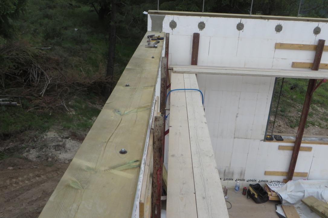
 The next two pictures give a couple of views looking right then left from the top of the main floor wall...

 ...and below looking directly behind the house up my slope of land to the upper limit of my property line, just short of the denser main tree line. As mentioned earlier, my intention is to allow this area to settle over the next seasons, allowing for rain later in the year, then winter snow and freeze thaw action, and then decide how to finish. My thoughts at this stage are to possibly build a retaining wall using pressure treated lumber (resistant to ground moisture) and maybe cut a further terrace above that could be turned into a small fenced vegetable garden - fenced in order to stop the resident deer eating my vegetables.
 Meanwhile Jason's team set to work for the best part of three days, initially putting in place the sill plates over the new concrete wall. In addition, where they had been too late during the previous concrete pour to wet dowel all the threaded redi-rod connectors that will hold the 14"x14" rafter carriers (concrete dries too fast in our current high temperatures) they drilled and fixed those additional rods in place with an epoxy, and then built the load and non load bearing walls that I have previously mentioned (you'll see these in late pictures when I show you the loft floor construction).
In the photo below you can see the pressure treated sill plate (required for where timber comes into contact with a concrete structure) fixed to the rear concrete wall, one ICF tier lower than the outer wall, as the outer end of the floor joists both for the loft floor and the 4' cantilevered rear deck will sit on this wall. In the distance on the outer wall you can see the concrete embedded rod bolts in place for the LVL rim joist that will run along that wall.
 These next two pictures show the sill gasket and the acoustic sealant (never solidifies) that provides the permanent airtight seal between the transition of materials. The very long rod bolts are the aforementioned system that will bolt the 14"x14" timber rafter carriers to the concrete walls.

 Meanwhile work was busy in the yard of Damstrom Log and Timber Homes. I had partly been finishing off the sanding and anti-rust painting of a number of metal fabricated parts that I had picked up just over a week before that will tie together many of the roof timbers. In the first photo below you can see the rafter to valley connectors (it's all a bit dusty in a timber yard) and in the second photo many of the post to beam right angle connectors. The frustration of that one is on the Monday I had received a bill from that fabricator. While my bill, it was neither made out to me, nor was it itemised (merely a bland comment on supply of fabricated parts) and was for a figure of approx $9,000, twice what had been expected, or the quote I had from another fabricator who has a reputation for much greater reliability but also greater expense. Besides the fabricators clear reluctance, even inability to itemise a bill, I resented the fact I was clearly being "gouged" at the close of business. That lead to a level debate between me and that supplier, with my stating the bill had to be first correctly itemised, and second reflect fairer indicated pricing before I will settle. I expect that to be a drawn out matter.

 The main activity in Bob's yard was his finalising joinery on certain timbers in readiness for an initial three big hauls to my site on the morning of Wednesday 28 June (more are planned later), one using my new 18' trailer and two using another 30" foot trailer that I had hired in, so that we had sufficient materials in readiness for the crane that Bob had hired to be on my site at 1PM that day.


 This Wednesday 28th booking was already a short notice change of plan by the crane supplier (Sandor Ltd), as the original booking was for Thursday 29th, but late on the previous Tuesday afternoon, the crane supplier had said they needed to change the booking. Much juggling by Bob Damstrom on my behalf with a number of my contractors to do the lift on Wednesday. I departed Bob's yard with my load just after 11AM, got back to my site, only to find Bob had received a call from Sandor saying no longer available that afternoon (I can only presume they had overbooked). To say none of us were happy would be an understatement, least of me as I now incurred a bill for the 30' trailer for time getting it to Bob's site, loading, and waiting! Further, without the 30' plus central column you see sitting on top of the load in the last photo, Jason's team ground to a complete halt as unable to build the loft floor without it - and so we lost the next two working days, plus the following Monday as a public holiday for Canada Day (Canada's 150th anniversary).
Bob Damstrom, Al (the 30' trailer contractor) and I used part of the public holiday to re-jig the haul of two 30' loads, plus my coming back for an 18' further load with my trailer, and then Tuesday early morning Bob drove his slow zoom boom along the back roads for 90 mins to my site. The crane turned up just after 8AM and was used over the next couple of hours, as follows.
Here you can see the central column hanging above the house and being lowered into place. The object at the top is the steel fabricated part that will cradle the house ridge beam and at 90 degrees to that the ridge beam that goes out over the stair well and then above garage open deck.
 Positioning it above the 12"x12" hole in the main floor ...

 In the basement, talking it down onto the metal pad and knife plate that goes into the ready cut notch in the middle of the 12"x12" (you can pick out the pre-drilled bolt holes in both the metal and the 12"x12" column ).
 Finally in place, but slightly scratched as the space made in the main floor had been too precise a fit.
 The crane was then used to lift the huge triple layer 18' deep dropped LVL beam into its beam pocket in the outer concrete wall, and at the opposite end on top of a built up column in the new load bearing framed wall (you can just see this on the right hand edge of the photo).
 The final job for the crane in the space of a mere two hours was to lift the garage end post that will support the far end of the garage ridge beam. In this photo below you can see it suspended and being lowered onto the metal horizontal flat pad that was attached to that concrete wall long ago (my post on 21 May "A bit of this and a bit of that"), again with its vertical knife plate that goes up inside a slot cut into the column, for subsequent bolting.
 Bob then dispatched the crane to save on his expense, and using his zoom boom proceeded over the next two days with some initial work assembling timbers on the garage deck while largely keeping clear of Jason's team, who now, with the central column in place, were able to proceed with the building of the loft floor.
Here Bob's assistant, Kevin, is guiding Bob while lowering a rafter carrier onto two supporting posts, themselves supported and now bolted to another of the metal column supports that were fitted to the concrete wall in May.


 Below you can see the column to rafter carrier connectors.
 The bolting system throughout relies on 6", 12"or occasionally 18" lug bolts as shown here, or in other areas use of galvanised threaded redi-rod cut to size.

 At the end of two days work, Wednesday 5th, Bob had achieved what he could and had to step away until Jason's team complete both the loft floor build and Big Foot sono tube footings. The latter will provide the base support for five of Bob's posts as part of the front 12' deck structure and the front roof overhang. Bob's plan is to return next week to initially build the front deck and roof end posts, and then later in the week will (we hope) have a crane on site to lift the remaining posts, rafter carrier beams, the big ridge beams, two valley beams and rafters into place. Here in the next two photos below is the initial post and beam system in place for the garage roof deck.

 Immediately prior to departing, Bob and Kevin kindly offered to trim three trees of their lower branches as these were partially obscuring the view south down the lake towards Montana on the second half of my garage roof deck. I had debated long and hard on whether to fell this 3 trees, but decided ultimately this was the more "green" environmentally sound option.
 Now I can see that view from the end half of that garage deck.
 Meanwhile, Jason's team were focussing on the loft floor build. With the central column now in place, they had to notch a join 3" deep, 8" wide and 12" high into which ...
 ... a quadruple LVL beam was then inserted on each side, right hand side sitting in another concrete wall beam pocket, and left hand above a built up column in the load bearing wall that separates the open plan area from the stair well.

 ... and the rear section joists supported at front end by hangars on the LVL beam that sits either side of the central column, and the back end of the joists sitting on the rear wall.
 There is however one significant change to what readers may have observed when I described the main floor build in an earlier post. This loft floor will have a small cantilevered 4' deck at the rear for my master bedroom. In the photo above you will note the start of this cantilever system, where the strand web between the joists is infilled with 1" thick plywood, then, as shown in the three photos below, the Fir timber joists are screwed to that infilled structure using numerous GRK timber screws.


 The Fir deck timber joists are 12' long, allowing a 4' deck and internal 8' cantilever. You'll note they have only been stained at the exposed end, all internal timbers requiring no stain or paint protection, as long as kept in dry environment.
 As in the main floor, the sub floor up here consists of ¾" select Fir plywood T&G screwed down to the joists.
 While focused on the loft floor, Jason's team also had to get the five Big Foot 28" sono tubes in place in order to allow Bob Damstrom to carry on next week with his post and beam system. Dale came back up on Wednesday 5th July to dig the five holes in the positions that Jason had carefully marked out in order to tie in with Bob's drawings.
 The Big Foot 28 footings have a 28" radius and have to be dug sufficiently deep so as to be both on original undisturbed soil prior to us having moved soil all around the site, and in much the same manner as the houses footings, they have to be at least 4' below grade in order to be protected from ground heave during the winter freeze thaw action. Much as before, we found the soil to be very rocky and firm - extremely good load bearing ground.

 Above the footing is a 12" tube. Both the footing and the tube will be filled with a certain amount of rebar reinforcement prior to a pour of 25Mpa concrete.
 Jason meticulously measuring for vertical and horizontal alignment in order to tie in with Bob's post and beams.

 Two days later on the Friday afternoon, a small load of concrete arrived, but this time no need for a pump truck as the concrete can simply be poured direct into the tubes.

 The system is reinforced by the inevitable rebar, a grid at the base and then 4 vertical pieces.

 Smooth trowelling on completion....
 ... and then placing the metal supports for the Fir columns into the wet concrete. These have the inevitable knife insert that will go up inside a cut in each post for subsequent bolting, plus a similar length going deep into the concrete. The system is designed to deal with not just horizontal loads, but vertical loads from wind or seismic pressure.
 The seismic comment above was timely as on Thursday 6th at 0030 local (0630 UTC) we felt an earthquake, a 5.8 which took place approx 150-200 miles south in Montana. http://www.cbc.ca/news/world/montana-alberta-earthquake-1.4192408 It was mild but enough to wake me and initially wander what was going on. Apparently the next mornings local Facebook chatter (I wouldn't know) was enormous as most people round here keep telling me we don't get earthquakes, to which I had always responded that they needed to review the NRCAN website data to see that they do, just not very often and normally fairly mild - unlike the west coast. One of many good reasons for my decision to build here.
At the end of a busy but disjointed two weeks (thanks to the let down by the crane supplier) a photo of the view looking up at the house. Much still achieved, but could have done without the downtime of wasted days waiting for the crane.
 Today, I had two calls/emails from family and also two friends asking about the BC wildfires they had seen on the BC news. http://www.bbc.com/news/world-us-canada-40534648 Suffice to say, much further north in BC there is a big problem, but this is something that in a semi arid but forested region you have to both monitor daily and have a plan in place for evacuation. I monitor this site twice daily at this time of year. http://apps.gov.bc.ca/pub/dmf-viewer/?siteid=5131184402955244847 Looks nasty up north, but in my area right down in the bottom SW corner of BC, one minute (0.01 HA) fire up near Kimberley and another about 25 km south of me, so far so small I anticipate they will be put out and not grow into anything that might become a threat.
I shall aim to post again in two weeks, weekend of 22-23 July, by which time I am hoping much of the raw timber parts of the roof structure will be in place.
Au Revoir.
During the last two weeks it was also extremely hot, with afternoon shade temperatures up at 36C, so imagine working in the blazing sun. Physically quite draining, although I am only too glad that it's a dry heat here, not humid like on the east coast.
Dale Bryant came back in on Monday 26th June to undertake the back fill of the rear basement wall. In the photo below I am standing in the trench close to the new window well for the inside rear bedroom and keeping a close eye open for large rocks that might fall against the waterproofing tarpaulin and risk tearing it. You can just see beneath the in-fill the deep layer of electrical grade sand that is covering and protecting both the main hydro (electrical) cable and water line that goes along the back footing to the point of entry into the mechanical room.

Backfill completed, here is a view from the NW corner, looking down the left side towards the lake.


In the photo below you can see the pressure treated sill plate (required for where timber comes into contact with a concrete structure) fixed to the rear concrete wall, one ICF tier lower than the outer wall, as the outer end of the floor joists both for the loft floor and the 4' cantilevered rear deck will sit on this wall. In the distance on the outer wall you can see the concrete embedded rod bolts in place for the LVL rim joist that will run along that wall.


Bob Damstrom, Al (the 30' trailer contractor) and I used part of the public holiday to re-jig the haul of two 30' loads, plus my coming back for an 18' further load with my trailer, and then Tuesday early morning Bob drove his slow zoom boom along the back roads for 90 mins to my site. The crane turned up just after 8AM and was used over the next couple of hours, as follows.
Here you can see the central column hanging above the house and being lowered into place. The object at the top is the steel fabricated part that will cradle the house ridge beam and at 90 degrees to that the ridge beam that goes out over the stair well and then above garage open deck.


.... and then on through down to the walkout basement.


Here Bob's assistant, Kevin, is guiding Bob while lowering a rafter carrier onto two supporting posts, themselves supported and now bolted to another of the metal column supports that were fitted to the concrete wall in May.

Here, with assistance from Jason's team, Bob and Kevin are lowering one of the 14"x14" rafter carriers onto the sill plate and long rod threaded bolts embedded in the front concrete wall, in the area immediately above the stairwell on the wall adjacent to the over garage deck roof.

In this photo this is the top end of one of those long rod bolts (nut not caught on my camera).


Where bolts are securing metal type connectors, normal washers are used, but where going into wood alone, special timber washers are used as shown here.


The subsequent fitting of the floor joists has them running front to back of the house, the front end supported as you see here by hangars on each transverse LVL beam ...


At the end of a busy but disjointed two weeks (thanks to the let down by the crane supplier) a photo of the view looking up at the house. Much still achieved, but could have done without the downtime of wasted days waiting for the crane.

I shall aim to post again in two weeks, weekend of 22-23 July, by which time I am hoping much of the raw timber parts of the roof structure will be in place.
Au Revoir.
I gather you have now buried all the bodies in the backfill? Perhaps you should have saved a hole for your 'fabricator' 😜. Recommend a pre-wetting system for the potential bush 🔥!
ReplyDelete