Huge timbers in the sky
Since my last post on Sunday 9th July, the BC wildfires further north have continued to rage, often with devastating effect. I think current tote is 150+ fires, most manageable by the firefighters, but some out of control at 3000 to 4000 HA (30 to 40 km sq), and one of nearly 50,000 HA (500 km sq) up in one of the remote parks. To give those readers back in UK a feel for scale and distance, BC is 944,735 sq km and UK (which at this date still includes Scotland) is 242,495 sq km, so BC is roughly 4 x the size of UK. The map below gives an overview of where the fires are today in relationship to my location at KCR (Koocanusa Ranch) down near the US border. Of the bigger fires, 100 Mile House is approx 600 km away as the crow flies, and Williams Lake about 800 km away. Williams Lake is a town of 10,000 people and was evacuated a week ago as a precaution. Down here, so far, we have been fine, with a couple of small fires within 40 km of my location that were quickly extinguished. My current nearest wildfire is about 80 to 100 km to the east of me just this side of the Crowsnest Pass, a small 3 HA fire. While air quality has been good the last few days, we did have a few days earlier this week where visibility was markedly reduced by the smoke being blown down from the north.
 As I think I said in my last post, I have a routine of checking this link http://apps.gov.bc.ca/pub/dmf-viewer/?siteid=5131184402955244847 each morning and evening, just in case lightning or some idiot who chooses to ignore the camp fire ban or just carelessly chucks away a cigarette, ends up starting another fire nearer to me. It's a seasonal summer risk and one has to monitor and always be prepared. Hopefully in the 10 years I plan to be here, I will be fine - in the scale size of BC, most are, but having had one devastating flood in my life while living in a desert (Tropical Cyclone Gonu, Oman, 6 June 2007) I hope to be spared another natural disaster.
Progress on my build over the last two weeks has been particularly pleasing and I now feel the vision of what the house will be is coming to life. In my last update of two weeks ago I left you with this photo showing just a few of the initial post and beam timbers in place.
 Since then, the supporting posts and many of the joists for the great room front deck have been installed, and all of the remaining posts and beams plus the rafters that make up the roof structure, all of which will be exposed when the house is complete to give it maximum wow factor.
Starting Monday 10th, both Jason Olesen's and Bob Damstrom's teams worked alongside in mutual support, getting the key structural posts into place. While the post and beam system is Bob's "part of ship" there is a need for some cross pollination of work as certain parts of Bob's post and beams link into Jason's work for his subsequent wood framing of the front prow wall and three gables (these will be built in conventional wood framing materials rather than ICF). Once their combined work was complete, Jason's team went off site end of Wednesday 13th to start the footings for another clients garage, leaving Bob the safe working space to crane the valley beams and rafters into place. I am anticipating Jason's team back on site middle of next week.
The first part of this last two weeks effort was getting the front deck main structural parts in place, not just as a part of building that deck, but because two of the 8"x8" posts extend from the concrete sono tubes up through the deck to the ends of the 14"x14" rafter carriers that support the front roof overhang. As shown in the photo below, these posts initially sit on a knife plate embedded deep in the concrete that then goes up into the middle of the post and is then bolted through using threaded galvanised redi-rod bolts and timber washers.
 Then at the top end of the post at deck level a further knife plate, as illustrated in this photo below ...
 ... is fitted and bolted into both the top of the lower post ...
 ... and the deck outer cross beam....
 ... and then the next post that will support the rafter carrier for the front roof overhang. The photo below shows the basic outline of the deck post and beams before the joists are put in place.

 Typically deck joists get attached to the wall rim joist by rather ugly metal hangars. Such a system would be a complete eyesore when looking from below in the vicinity of my front main entrance and the walk out patio, so in this build a system of pressure blocking using timber GRK fasteners and wood blocking is being used to provide support to the inner joists. I'll have a lot more staining of the deck timbers to do when Bob has finished the deck build.
 Next task was to get the remaining 14"x14" rafter carrier beams into place on the top of the concrete walls. You can see below one being lifted into place, below. The black beading on the sill plate is more of that non hardening acoustic seal that ensures a permanent airtight seal should the timber contract.
 The rafter carriers were pre-drilled to site over the rods previously embedded in the ICF walls during concrete pour ...

 ... and then bolted down. In the next photo you can see one of the two rafter carriers that extend out from either side of the prow wall, supported by the aforementioned posts coming up through the deck system, ready to support the rafters at the front roof overhang.
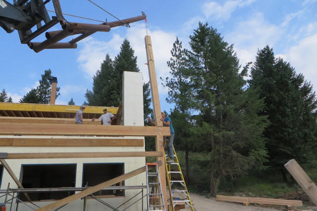
 Next job was to site the 12"x12" structural column that sits on the centre of the prow wall in line with the huge basement to roof central column that you may recall was lifted into place a few weeks ago (see my last post). This column will be exposed in a framed wall, but as per my engineers requirement, had to be further thickened by layers of 10"x10" lumber nailed at 16" spacing, both to fit the ridge beam and add further lateral strength to the prow wall as mitigation against wind sheer or seismic effect. (The additional 10"x10" lumber will be hidden in the framed wall).


 Once built up, the column was then lifted into the air ...

 ... and sited over a knife plate previously bolted to the concrete wall.
 ... and then trued for vertical alignment and temporarily braced on three sides.

 Subsequently, as shown in the photo below, the prow walls at either side had two further 10"x10" plates bolted to the concrete, eight hangars fixed to the plates, and then those four yellow 9½" deep triple (a total of 6") thick LVL (laminated veneer lumber) headers lifted and secured into the hangars, effectively now bracing the central column and front prow wall. You can now get a sense of the panorama that will be provided through the two 12' wide glass sliding doors and two awning transom windows.
 Over the next two days another post was lifted into position in the middle of the over garage deck, plus one on top of that concrete wall that separates the loft level of the house from the underside of the garage deck. The central garage deck column transmits its load roof load through blocking in the deck to the steel column in the middle of the garage (you will recall this was installed much earlier in the build) and down to the 12" deep rebar reinforced concrete pad. There was also much measuring, calculating and rechecking over these two days so as to be sure everything was trued before the following weeks work.
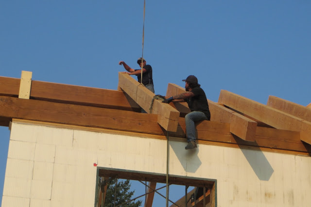
 Monday 17th saw the task of lifting the ridge beams (essentially shaped 20" Fir tree trunks) into position. Bob's team started on site at around 0600 in order to work before the worst of the heat of the day, and by the time I turned up on site at 0800 the ridge beam from the back of the house to the central column was already in place. Here is the second piece extending from the central column to the front prow being hoisted into position. You'll note the smoke haze over the far mountains that is being blown down from the aforementioned wild fires 600 km to the north.


 Next task was to lift and position the ridge beam that goes out at 90 degrees to the main house over the stairwell and garage roof deck.

 This ridge beam comes as another two sections, supported in four areas - the main central column, a column on top of the concrete wall outside the stairwell, a column in the middle of the garage deck and a post on the outer garage concrete wall. In the second of the photos below you might also just be able to see a notch cut in the underside of the first section - this is where a further built up column will be positioned and hidden in the right hand framed wall of my loft master bedroom.


 Here, in spite of the thin smoke haze, is an amazing view looking from the slope behind the house over the garage deck roof ridge beam.
 Next task was to lift the two 12"x16" valleys into place ...
 ... with the obligatory mucky non hardening acoustic sealant ...
 ... and then lift and fit the shorter valley rafters into their metal hangars on the valleys.
 Here Kevin Fox (working for Bob during this roof project), both an artist and a deft handler with any chain saw, and a man with absolutely no fear of heights (unlike myself), is undertaking a bit of refined trimming of one of the full length rafter ends, prior to its adjacent short valley rafter being lifted into place.
 Tuesday 18th was a day without the crane on site while Bob's team precisely measured and prepared for the hoisting and positioning of all the full length 6"x12" rafters. These, with one or two exceptions, are spaced at 48" on centre.
Wednesday 19th, crane back on site for six hours. Initially rafters were lifted as singles, and then as bolted pairs. The gap you can pick out to the right of this next photo where a scaffold is in view has no rafters. A shed dormer will be framed here in the next few weeks to provide a full head height space for my en suite bathroom and walk in closet.


 Main house rafters hoisted, the same process carried on over the stairwell and over garage deck roof.

 Crane off task at the end of Wednesday 19th, Thursday day was dedicated to final positioning, trimming, and then bolting down all the main timbers and rafters. Throughout some of the pictures above you will have noted the huge plate that sits on top of the central column with its lug bolts holding the ridge beams in place. You may have also noticed a number of steel right angle plates at the top of each post are the means of securing the posts to the rafter carriers and ridge beams over the open garage roof area where there is no concrete wall. The two 12"x16" valleys that sit on top of the ridge beam are bolted down with 16" lug bolts countersunk into the valley by 4" so as to ensure a 4" purchase in the ridge beam. In a similar manner each rafter is connected to both the ridge beam and its opposite rafter. While not shown here, a further system of hurricane strapping is used over the top of certain key areas, such as the joins in some of the ridge beams and rafter carriers.

 As an aside, in the last photo you'll notice way down below under the tree just one pile of all the off cuts of various bits of lumber used over the last few months during the build - enough kindling wood for my wood burning stove for at least a couple of years.
Friday 21st was dedicated to plumb lining and trimming all rafter ends to ensure an exact and aesthetic straight line as you look along the roof line, plus trimming a couple of rafters that were slightly high on their upper side when compared to the next rafter (would have made it difficult to lay out and fix the 16' pine T&G spans over each of four rafters). Effort was also focussed on laying out the initial two runs of T&G ready for next weeks fitting of all the T&G over the entire rafter system. Readers will recall the work I and Chris Walch put in many weeks ago clear staining (varnishing for UK readers) all the pine T&G (see post dated 4 June).
All these phenomenal timbers plus the T&G that will go on top of the rafters next week will remain fully exposed when the house is finished. In the next 2-4 weeks I should be able to show the framing of the insulation space above and ultimately the fitting of a metal roof. But at this stage, at the end of a busy two weeks, here are some pictures of the result so far.
In this photo we are looking with my back to the houses left hand wall under where the bathroom shed dormer will be built (hence there are no rafters above me in this area) on past the main central column into the loft bedroom area. The slope of the valleys means that the effect will be slightly cave like, 10 foot plus in the middle but with a loss of headroom on the right hand side, but the layout and relatively large floor area still affords sufficient headroom either side of even a 6' wide king sized bed. The plan is to have an internal window in the framed wall that will go on top of that beam you can see at the end of the loft floor, to provide added ventilation from the stair well, and then in the next gable wall two trapezoid windows that will give a view under the over garage deck roof.

 This photo is taken from what will be the gallery outside the loft bedroom, looking towards where the stair landing will be.
 And here looking from the gallery area through the front gable wall where big trapezoid windows will allow much of this view. As mentioned earlier, the 12"x12" column will be exposed but not the additional 10"x10" thickening or LVL window ledgers. I am undecided yet, but I may have a further internal ventilation window in the framed wall at the front separating the loft bedroom from the gallery landing that would let me to enjoy the view from my bedroom as I surface from my slumbers each morning.
 Two aspect views of the garage deck roof.

 Finally, a view looking up at the front of the house. I think this is just awesome!
 In addition to fitting the T&G next week, having taken delivery of more materials on Friday afternoon, and subject to Jason's team returning on site middle of this next week, I am anticipating when I next post weekend of 5-6 August, the front, back and stair well gable walls will be framed, and we may have started the roof insulation framing as well. I also hope we will have the slab plumbing and radon mitigation roughed in, as this is a precursor to subsequent work that has to be done to insulate the slab and fit the slab hydronic heating loop prior to slab concrete pour.
Until next my next update, tally ho!

Progress on my build over the last two weeks has been particularly pleasing and I now feel the vision of what the house will be is coming to life. In my last update of two weeks ago I left you with this photo showing just a few of the initial post and beam timbers in place.

Starting Monday 10th, both Jason Olesen's and Bob Damstrom's teams worked alongside in mutual support, getting the key structural posts into place. While the post and beam system is Bob's "part of ship" there is a need for some cross pollination of work as certain parts of Bob's post and beams link into Jason's work for his subsequent wood framing of the front prow wall and three gables (these will be built in conventional wood framing materials rather than ICF). Once their combined work was complete, Jason's team went off site end of Wednesday 13th to start the footings for another clients garage, leaving Bob the safe working space to crane the valley beams and rafters into place. I am anticipating Jason's team back on site middle of next week.
The first part of this last two weeks effort was getting the front deck main structural parts in place, not just as a part of building that deck, but because two of the 8"x8" posts extend from the concrete sono tubes up through the deck to the ends of the 14"x14" rafter carriers that support the front roof overhang. As shown in the photo below, these posts initially sit on a knife plate embedded deep in the concrete that then goes up into the middle of the post and is then bolted through using threaded galvanised redi-rod bolts and timber washers.


The photo below shows the basic outline of the deck post and beams before the joists are put in place.

The deck will extend from the great room with a walk way around to the over garage concrete deck.


Wednesday 19th, crane back on site for six hours. Initially rafters were lifted as singles, and then as bolted pairs. The gap you can pick out to the right of this next photo where a scaffold is in view has no rafters. A shed dormer will be framed here in the next few weeks to provide a full head height space for my en suite bathroom and walk in closet.


Friday 21st was dedicated to plumb lining and trimming all rafter ends to ensure an exact and aesthetic straight line as you look along the roof line, plus trimming a couple of rafters that were slightly high on their upper side when compared to the next rafter (would have made it difficult to lay out and fix the 16' pine T&G spans over each of four rafters). Effort was also focussed on laying out the initial two runs of T&G ready for next weeks fitting of all the T&G over the entire rafter system. Readers will recall the work I and Chris Walch put in many weeks ago clear staining (varnishing for UK readers) all the pine T&G (see post dated 4 June).
All these phenomenal timbers plus the T&G that will go on top of the rafters next week will remain fully exposed when the house is finished. In the next 2-4 weeks I should be able to show the framing of the insulation space above and ultimately the fitting of a metal roof. But at this stage, at the end of a busy two weeks, here are some pictures of the result so far.
In this photo we are looking with my back to the houses left hand wall under where the bathroom shed dormer will be built (hence there are no rafters above me in this area) on past the main central column into the loft bedroom area. The slope of the valleys means that the effect will be slightly cave like, 10 foot plus in the middle but with a loss of headroom on the right hand side, but the layout and relatively large floor area still affords sufficient headroom either side of even a 6' wide king sized bed. The plan is to have an internal window in the framed wall that will go on top of that beam you can see at the end of the loft floor, to provide added ventilation from the stair well, and then in the next gable wall two trapezoid windows that will give a view under the over garage deck roof.


Until next my next update, tally ho!
Glad to hear the pre-wetting system may not be required. Exciting stuff shippers, starting to look like a real house now rather than a range bomb shelter. In the interim, good to see in one of the many photos that the principle of 'get a bigger hammer' is alive and well on your project. 🤣
ReplyDeleteAs for "bigger hammer" I rather like the one with Kevin Fox sat on top of the ridge beam doing a bit of trimming with a humungous chain saw. There is nothing small or delicate about this build.
DeleteKev can do some amazing carved arty woodwork pieces with that machine. I am thinking of asking him later this winter to carve out a king size bed headboard with an Osprey or Cougar (appropriate) as the central theme.
I think an old cougar or MILF would be an entirely appropriate bed headboard ahahahahaha
Delete