Returning from UK on 28 February it was immediately evident as I came out of Cranbrook airport that plans to start second week of March were just a tadge ambitious. The snow was still many feet deep and it remained icy cold. So I filled the next couple of weeks looking over my plans, a trip to Calgary to review my window order with my selected supplier and further refine my kitchen design, and also to have a bit of city weekend before becoming fully focused for several months on building out in the sticks.
Excavation commenced week of Monday 20th March for 3 days, cutting in the drive up the steep incline to my build site, removing the root stumps of the trees I had felled the previous September, preparing the build site, and digging the trenches for the stepped footings (explanation to come later). Fortunately the early winter heavy dump of snow had effectively blanketed the ground before a deep freeze could really enter the soil, but within an hour of starting to dig, water and mud was flowing.
 |
Cutting in the entrance to the driveway.
|
 |
The ascent.
|
 |
It rapidly became a mass of wet glutinous mud.
|
 |
As did the ground while flattening the build site and digging down for the daylight walk out basement.
|
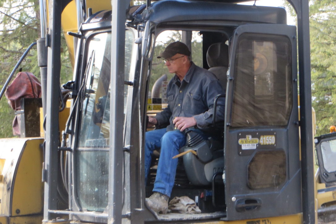
After two days we took a one day break to allow some of the water and mud to drain away. A day later with the sun out and some early spring warmth in the air, both my excavator (Dale Bryant) and concrete and framing contractor (Jason Olesen) worked in impressive unison to level the build site and shoot the initial grades and final dig of the stepped footings. With improved weather, work now underway after 7+ months of planning, and also the clear evidence that I had chosen two good contractors capable of working well together, I had an absolute buzz of enthusiasm, only occasionally punctuated with those moments when Dale was constantly battling with his excavator's shovel to break through large lumps of rock. One of the big fears on this site had been that we would hit heavy bedrock that would then require blasting. While perhaps claiming a background that might enable me to blow this up myself, I would be neither able to get the "bang" nor would it be legal for me to do so, and so I was bracing myself for additional expense. But Dale managed to break through and shatter the rocks each time, and the comfort I now have is that my footings will be very well supported by such solid ground.
 |
Jason Olesen setting up to shoot grades, with Don in the picture below (one of his team) doing the easy bit.
|
 |
| Dale doing battle with bedrock. |
 |
In this photo you can see the flat basement area with the built up land at the rear and open walkout at the front, and the trenches for the stepped footings.
|
 |
Excavation of the two deep pads in the centre of the house and garage that will support two central columns for the two roof systems.
|
On completing excavation work we held a wash-up discussion. Looking at how sodden the ground was from melt water, we all agreed it would be best to allow things to drain for a few more days, especially on the new driveway. In addition, rather than following the initial plan to pour ¾" gravel, which would just sink into the mud, we would bring in several truck loads of 2" to 5" broken up slate rock in order to provide a much firmer base that would better support the forthcoming heavy trucks, and leave the ¾" rock as a subsequent driveway dressing until after the main build. You can't beat mother nature and her weather, and certainly the advice, while costing me another $1,200 in rock, has proved wise counsel. The rock was delivered, dumped and spread across my driveway middle of the next week (Wednesday 29th March). As you can see in the photo below, the ground was instantly transformed into something very solid, which would provide a very firm base for the concrete trucks and pump 12 days later.
Driveway now transformed, work then continued for another week, refining the grades, building the wooden forms for the footings, and fitting the rebar (reinforced steel bars) ready for concrete pouring.
To explain a little bit about the reasoning behind the stepped footings and the two central pads you saw being excavated in the photographs.
Basements are rare in UK due to the high water table, but in Canada, with the exception of the far north where there is permafrost, basements tend to be the norm. Basements are part of a combined footing and foundation system, and ensure that the house remains properly supported well below the winter freeze thaw action and consequent ground heave that would otherwise destroy the house. Depending on area of the country, generally these footings need to be anything between 4 and 6 feet below ground. Historically basements tended to have low headroom, but ultimately building practises capitalised on this space by building full height basements that could be finished as proper living spaces with well windows high up near grade (ground level). My house, being built on a hill, will have a basement that will be conventionally buried at the back of the house with well windows, but allows for the slope with an eventual daylight walkout at the front. As such, the front looks to all intent and purposes as if it is at traditional ground level. But in order to ensure the footings at the sides and the actual front wall remain well below the frost line, they are stepped with the slope, and become progressively deeper at the front compared to the rear wall where the higher land already has them naturally deeper than the frost line.
As for the two massive central pads you saw being excavated in the photographs, one in the middle of the house, and one in the garage. These will be deeper than the footings and have even more rebar reinforcing prior to concrete pouring, in order to support a significant point load through a column from both the centre of the house roof and the separate garage roof, along with the covered flat concrete deck immediately above the garage. There are also smaller pads that are within the perimeter footings, in order to provide point support to side columns that support the roof system.
 |
| Initial Architects Footings Plan |
 |
| Initial Architects Wall Plan |
As you will see in the next set of site photographs, as part of my engineers structural specification that supplement and overrides the above initial architectural proposals for footings and foundation walls, the perimeter footings contain 3 horizontal bars, with the additional perimeter pads supporting roof columns, and dependant on their location having anything between 4 and 6 bars in one direction and the same at 90 degrees, and in the case of the two central pads, 7 bars each way. The perimeter footings are 2 ft wide, enlarged at the pads and 10" deep, and the house and garage two central pads are 5' x 5' square and 12" deep. The house central pad ended up being 18" deep due to the battle to scrape a rock away and the hole it left. While this adds a significant amount of concrete, this was more cost and time effective than the alternative of infilling and compacting soil and then getting a GeoTech on site to approve. I have to say that with 18" of reinforced concrete as opposed to 12" supporting the centre of my roof ridge beam, I will be even happier with that thought at night!
For those from a walk of life like me who are interested in how systems and machines work, even if not an engineer, you can click to enlarge the following two pages from my engineering structural drawings to look through the detail and logic. For those artists where this is totally over-powering, I am sure my later snap photos will be quite enough for you!
 |
| Engineers Structural Foundation Plan |
 |
| Engineers Structural Lower Wall Plan |
The following pictures show the wooden footing forms in place with 15 mm rebar reinforcing laid out. In addition you will see the initial vertical rebar already in place as the start of the ICF lower level foundation wall system. Not always required, the engineer wanted this to be tied into the footing rebar instead of being wet dowelled later during the concrete pour, as he considered that this further mitigates risk of shear. Vertical spacing varies, and is often significantly above building code requirement, again at the behest of my engineer. For example in the side walls it will generally be at 18" vertical spacing (code) but in the back filled back wall at a stronger 12" vertical (this is above building code), and in the front prow wall at an incredible 6" spacing. The engineers argument for the front wall vertical spacing was to provide maximum strength against wind and seismic forces for the built up end column carrying the huge ridge beam and roof overhang above the front deck in a prow wall with a lot of glass. Seems fair, despite the added cost.
 |
| House left hand side footing (when you face the lake), stepped at 3 levels to allow for slope of hill. The side wall has 3 horizontal bars and the start of the 18" vertical rebar that will be in the main ICF wall, then as you come round to the front prow wall that vertical spacing reduces to the high spec 6". |
 |
| Garage right hand side footing (when you face the lake), stepped at 3 levels to allow for slope of hill. Vertical rebar in both the garage side and front foundation wall at 18" spacing. |
 |
| Front prow wall footing, again with standard 3 horizontal bars of rebar, but this front wall has 6" vertical rebar spacing changing to 12" spacing as come around the right hand edge towards the main foyer entrance. |
 |
| This is the right hand footing (as you face the lake) between the main house and lobby. Not an ICF wall but a framed load bearing wall which will contain several hidden built up columns to support the roof system, of which the pad you can see supports the thickest. The footing in front of the camera will support the stair case header. |
 |
| Garage and house rear footing with some thickened pads evident that will support columns for the roof system. |
 |
| Footing supporting ICF wall between garage and main house. Note the drop at front to line up with front wall, and that there is a step between the house and garage of 1' (It is building code requirement that garage is below the house slab). |
 |
| The house central pad for the column that will provide centre support to the ridge beam. |
After roughly a week of all this preparation work, the real fun that I had been looking forward to came on Monday 10th April. A concrete pump truck on site and just under 20 tonnes of concrete being delivered in loads with Jason's expanded team on site to spread and smooth trowel it so as to offer a perfect surface for the ICF walls. (While I had helped with various bits of practical work over the last week, on trying my hand at smooth trowelling the concrete, Jason tactfully suggested I hadn't quite got the technique that was needed - I don't know what he meant).
 |
| The concrete boom pump truck and first concrete delivery. Grown up men's toys. |
 |
| One man handling the pump truck boom delivering the concrete and Jason using a sonic vibrator to ensure cement, water, other additives and the aggregate all mix and settle correctly, leading to greatest Mpa strength. |
 |
| That 18" deep rebar reinforced central pad - done in 3 pours. |
 |
| Job done after 4½ hours labour, 5 men, one pump truck and driver, and 4 and a bit concrete truck deliveries. |
 |
| Peace and quiet again, the residents before me move back on site to feed. |
 |
| "What's your problem Mr Woodward? I was here first". |
 |
| "I live here too". |
With the fun part over, over the next two days we stripped the wooden forms off the new concrete footings and then nailed wooden battens on the top in order to mark and ensure the future ICF walls will be absolutely straight. Any minor error at start multiples as the wall length and height goes up, and Jason continued to impress me with his attention to this detail.
 |
Looking South over the right hand wall of the house towards the garage at the far end.
|
 |
| Looking North from the garage side wall end. |
 |
| In this photo above we are looking straight down from the back of the house from what will be grade on the back wall. To the right at the rear will be two bedrooms with high well windows, and further forward will be the walk out family room onto a patio underneath the Great Room's 12' extended main deck. Slightly left of mid view at the rear will be a mechanical room (boiler, hydronic floor heating, water heater, water supply, heat recovery and ventilation system, etc), and in front of that the entrance foyer and stair well. To the right, just off the edge of the picture, the garage. |
On the last working day of the week (Thursday 13th April) before the long Easter Weekend, the ICF arrived on a 60 foot enclosed road transporter. Too big a vehicle to be able to drive into Koocanusa Ranch and then turn around on our private road, we backed it in at the main gate, 1.5 km away, unloaded, then in two and a bit shifts on Jason's trailer and Don's pick-up truck, drove it to my site, unloaded and then went back for the next load.
 |
| Chris Walch taking a look to make sure I was managing my site correctly. |
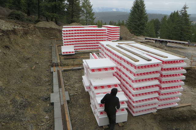 |
Approximately 4 hours work shifting from the main gate to my site, stacking, and ultimately weighted and tied down for wind (this stuff is light until its filled with concrete), job done and its "Le Long Weekend."
|
The best part of the next couple of weeks after Easter Monday will be taken up with setting the ICF basement walls, inserting ridiculous amounts of horizontal and vertical strengthening rebar, placing window and door bucks, then fitting temporary bracing either side of the ICF walls so that there is minimal risk of a form bursting when the concrete filling takes place.
I intend to post again sometime the weekend of 29-30 April.
Bientôt.


Looking good!
ReplyDeleteLeanne C
Wow! Those are some big machines. It is amazing just how much work goes into a project such as this. I showed my son the pictures of all of the work equipment and he was taken aback and how much earth they had moved. Good luck in the future and please post more pictures of the equipment!
ReplyDeletePleasance Faast @ Shelton Roof